 This guide was developed to instruct users on the proper method to install an ATA based optical drive into a desktop computer system. These instructions are valid for any form of optical based drive such as CD-ROM, CD-RW, DVD-Rom or DVD burners. It is a step-by-step instruction guide with photographs detailing the individual steps.
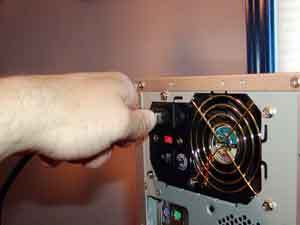
The very first thing to do whenever working on a computer system is to make sure there is no power. Shut down the computer if it is running. Once the computer has safely shut down, turn the internal power off by slipping the switch on the back of the power supply and removing the AC power cord.

This guide was developed to instruct users on the proper method to install an ATA based optical drive into a desktop computer system. These instructions are valid for any form of optical based drive such as CD-ROM, CD-RW, DVD-Rom or DVD burners. It is a step-by-step instruction guide with photographs detailing the individual steps.
The very first thing to do whenever working on a computer system is to make sure there is no power. Shut down the computer if it is running. Once the computer has safely shut down, turn the internal power off by slipping the switch on the back of the power supply and removing the
The very first thing to do whenever working on a computer system is to make sure there is no power. Shut down the computer if it is running. Once the computer has safely shut down, turn the internal power off by slipping the switch on the back of the power supply and removing the
AC power cord.
At this point, the computer needs to be opened up to properly install the CD or DVD drive into the computer. The method for opening the case will vary depending upone the case. Most new systems will use a panel or door on the side of the system while older systems may require the whole cover be removed. Remove and set aside and screws fastening the cover or panel to the computer case and then remove the cover

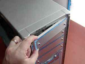
Remove the Drive Slot Cover
Computer cases can generally hold a number of external drives but only a few are generally used. Any unsed drive slot has a cover that prevents dust from entering the computer and makes the case look better. To install the drive, it will be necessary to remove a 5.25" drive slot cover from the case. Removal of these generally is done by pushing some tabs either on the inside or outside of the case. Some may be screwed into the case.
Computer cases can generally hold a number of external drives but only a few are generally used. Any unsed drive slot has a cover that prevents dust from entering the computer and makes the case look better. To install the drive, it will be necessary to remove a 5.25" drive slot cover from the case. Removal of these generally is done by pushing some tabs either on the inside or outside of the case. Some may be screwed into the case.

Setting the IDE Drive Mode
The majority of all CD and DVD drives for computer systems use the IDE interface. This interface can have two devices on a single cable. Each device on the cable must be placed into the appropriate mode for the cable. One drive is listed as the master and the other secondary drive is listed as a slave. This setting is generally handled by one or more jumpers on the back of the drive. Consult the documentation or diagrams on the drive for the location and settings for the drive.
If the CD/DVD drive is going to be installed on an existing cable, the drive needs to be set into the Slave mode. If the drive is going to reside on its own IDE cable alone, the drive should be set to the Master mode.
 Placing the CD/DVD Drive into the Case
At this point, the CD/DVD drive needs to be placed into the computer. The method for installing the drive will vary depending on the case. The two most common methods for installing a drive into a case is either through drive rails or directly into the drive cage.
Rails: Place the drive rails onto the side of the drive and fasten it with screws. Once the drive rails have been placed on both sides of the drive, slide the drive and rails into the appropriate slot in the case. Make sure to affix the drive rails so that the drive is flush with the case when it is fully inserted into the case.
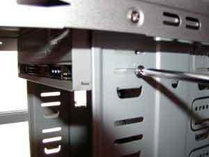
Drive Cage: Slide the drive into the slot in the case so that the drive bezel is flush with the computer case. When this is done, fasten the drive to the computer case by placing screws into the appropriate slots or holes in the case.

Attaching the Internal Audio Cable
Many people use the CD/DVD drive inside of their computer to listen to audio CDs. In order for this to work, the audio signal from the CD needs to be routed from the drive to the computer audio solution. This is typically handled by a small two wire cable with a standard connector. Plug this cable into the back of the CD/DVD drive. The other end of the cable will plug either into a PC audio card or motherboard depending upon which the computer uses for audio. Plug the cable into the connector labeled as CD Audio.

Attaching the Drive Cable to the CD/DVD
At this point, the CD/DVD drive needs to be attached to the computer through an IDE cable. For most users, the drive will reside as a secondary drive to the hard drive. If this is the case, locate the free connector on the IDE ribbon cable between the computer and the hard drive and plug it into the drive. If the drive is going to be on its own cable, plug the IDE cable into the motherboard and one of the other connectors of the cable into the CD/DVD drive.
At this point, the CD/DVD drive needs to be attached to the computer through an IDE cable. For most users, the drive will reside as a secondary drive to the hard drive. If this is the case, locate the free connector on the IDE ribbon cable between the computer and the hard drive and plug it into the drive. If the drive is going to be on its own cable, plug the IDE cable into the motherboard and one of the other connectors of the cable into the CD/DVD drive.

Plug the Power to the CD/DVD
The only internal item left to do for installing the drive is to plug it into the power supply. This is done by locating one of the 4-pin Molex connectors from the power supply and inserting it into the power connector on the CD/DVD drive.
The only internal item left to do for installing the drive is to plug it into the power supply. This is done by locating one of the 4-pin Molex connectors from the power supply and inserting it into the power connector on the CD/DVD drive.

Closing up the Computer Case
At this point the drive is fully installed into the computer case so it can be closed up. Replace the panel or cover to the computer case. Be sure to fasten the cover or panel back to the case using the screws that were set aside when the cover was removed
At this point the drive is fully installed into the computer case so it can be closed up. Replace the panel or cover to the computer case. Be sure to fasten the cover or panel back to the case using the screws that were set aside when the cover was removed
Powering up the Computer
All of the installation steps for the CD or DVD drive are now completed. The only thing left to do is return power to the computer. Plug the AC cord back into the power supply and be sure to flip the switch to the on position.
The computer system should automatically detect and begin using the new drive. Since CD and DVD drives are very standardized, it should not be necessary to install any specific drivers. Be sure to consult the instruction manual that came with the drive for any specific instructions for your operating system.


